


A recent webinar hosted by Siemens discussed a holistic engineering approach that covers structural analysis, CAD (computer-aided design) and CFD (computational fluid dynamics).
Such an approach has both technological and organizational benefits, that help cut costs, save time, always have project data at sync, and increase communication during the entire engineering process among different stakeholders.
Keeping project costs low during a large and complex design project is no small feat. In the case of designing naval vessels, the complexity of the vessels themselves is one reason. But there is more: it’s easy to run out of schedule, or not living up to the challenge, underperform, or even fail when project scope and costs are not managed well. Unfortunately, the current design spiral is far from efficient and silo-ed, consisting of different but related domains where it is often necessary to redo and reiterate things in order to keep all components consistent as a global system.
The trick is to get the right information at the right time and in the right context during the design process. Solving the different organizational and technological challenges requires a managed, integrated and collaborative approach consisting of two components: a simulation process and data management. The webinar demonstrated how the resulting engineering process would look like, with a focus on challenges for structural simulations and the software that can be used in this context from the design phase up to verification and certification of the simulations.
Towards an integrated end-to-end solution
As shown in the left part of Figure 1, typical unmanaged analyst environments exist in many different industries, with a sole analyst in the center of it all who needs to manage all applications, data and requests. The right shows the ideal solution, which would be a system that builds a framework from collaboration. With a connected digital thread, so that everyone knows what current statuses are, where tasks can be delegated and versioning is no longer an issue as data and models are kept in sync at all times. This approach enables designing across multiple departments and domains.
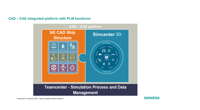
A typical process for marine structure performance engineering consists of disconnected systems where the design and loads for FEM simulations are brought together to other external tools to make assessments on whether or not the design is suitable. Siemens proposes an integrated end-to-end solution that is displayed in Figure 2, a CAD - CAE integrated platform with PLM backbone: the CAD - CAE is made up of two components: Simcenter 3D and NX CAD.
Simcenter 3D for structural engineering is a multiphysics platform with a multitude of solvers. It directly integrates with NX CAD, because it has been built on top of NX and it inherited its geometry engine, resulting in a seamless integration between the design and simulation world. The third element is Teamcenter that keeps track of the PDM and simulation data management.
Tackling individual sub-tasks of an engineering workflow in an integrated way
Figure 3 shows a typical engineering workflow, starting with a design in NX, doing the meshing, property definition, applying load cases, solving and doing post-processing and reporting. Each of these individual steps is followed up with the data management systems so that the traceability is always known, what the statuses are and that everything is connected with each other and in sync. In total, there are four tasks: initiate the ship structural analyst process, geometry preparation, FE model preparation and the loadcase definition.
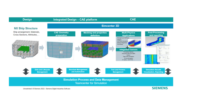
The webinar covered each individual task of the simulation process for structural performance assessment to show how the actual work looks like, how to access the tools from the platform to do the work and build a model.
Structural analysis process initiation
The process starts with initiating the structural analysis process through effective communication, collaboration and tracking. Using a model structure as a starting point for this, an engineering workflow is designed in Teamcenter. That workflow consists of different building blocks that contain information about what should be done and by whom. This way, Teamcenter Simulation is used for effective communication, collaboration and tracking through a connected digital thread, in order to seamlessly pass the right information to all teams, establishing transparency of program tasks and timelines and the ability to check progress and status.
Geometry preparation
The second step, the geometry preparation that is needed for the CAE, is done in NX, and can be started directly from Teamcenter. Through a “one-click” process, the geometry is made ready for meshing for a complete ship structure, ship section or area of interest: sheet bodies (panels) and geometry edges (stiffeners) are properly splitted and connected so that no gaps exist. Through this process, the right information has been put in the right context and is ready for meshing.
FE model preparation
The FE model preparation process includes hundreds and thousands of structural components. Defining mesh properties is a time consuming and error-prone process. But it is done in an almost completely automated fashion within Simcenter 3D. After that, everything is stitched together so the result is a closed system which is required for a structural analysis. A dedicated meshing application for ship structures directly inherits data from a CAD model (geometry and attribute information), meaning the different mesh elements and the CAD model are in sync.
Loadcase definition
The loadcase definition task realization can be potentially done with external tools. With Teamcenter and Teamcenter for Simulation, it’s possible to launch third-party tools, capture data coming from the result files of these tools and launch these. This means integration of external simulation applications, both commercial and inhouse. This process can also be automated through translation scripts, macros or programming interfaces. Through the whole loadcase definition task, Teamcenter can be the collaboration layer and starting point for simulation execution, where resulting data can be shared across teams.
Simcenter 3D offers templates for using standardized rules for load scenarios, to capture and reuse knowledge and apply libraries of expressions which can be made to fit the requirements of regulations. A set of selection recipes map in a smart way what’s defined below the loads, where they apply and how they are set up.
For local assessments that need to be made, Siemens also has tools that look into more detail into individual sections and derive reports whether or not there are issues in these local models, providing a scalable approach of global loads and projecting things down to local models.