


Most vessel designers and operators are familiar with the dangers that fatigue poses to ships and other maritime assets. The constant action of waves places incredible demands on structures. One particularly famous example is the fracture of whole hulls of Liberty Ships during World War II. After the losses of multiple ships, the causes were identified and mitigations put in place - rounded corners on hatch openings, addition of gunwale bars and other anti-fracture reinforcements, etc.
Designers have long had excellent tools for calculating the maximum loads on structures, and providing adequate scantlings to support them. Fatigue presents a special challenge; in the past we've relied on margins and rules of thumb or best practices to prevent fatigue failures. In multiple recent projects, Bristol Harbor Group has been able to apply explicit analysis techniques to improve on these traditional practices, and provide enhanced fatigue performance.
These techniques have five basic steps:
- Define the Fatigue Environment
- Develop Characteristic Vessel Conditions
- Perform Finite Element Analysis (FEA)
- Identify Stress Range Hot Spots
- Apply S-N Curves
- Design and Assess Mitigations
First, the expected fatigue environment needs to be defined - usually, the wave spectrum the vessel will encounter over its life. In more specialized applications, operators may be able to define the load and cycles that are expected. More often, historical data can be found for planned routes and areas of service. In US waters, wave height records can be found in the public archives of the National Data Buoy Center. These records can be analyzed and a best-fit probability curve for wave height can be constructed. A Weibull curve, as shown in Figure 1, is a good fit for most sea spectra.
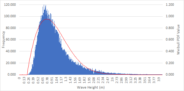
Figure 1: Weibull Curve (red) fit to buoy Wave Height data (blue)
Second, characteristic forces on the vessel - due to cargo weights & centers, distributions, etc. - need to be defined. The accelerations due to waves must be found via some form of seakeeping analysis. Crucially, both the high and low end accelerations due to sea state-driven vessel motions must be developed and applied. Using any of the common hydrostatics and stability software packages, the hydrostatic conditions of the vessel can be found when the resulting forces are applied.
Third, a Finite Element Analysis (FEA) of the vessel with the characteristic forces due to the high and low accelerations must be performed. This allows a stress range to be developed for any point in the structure, defined by the stresses in the high (Figure 2) and low (Figure 3) acceleration conditions.
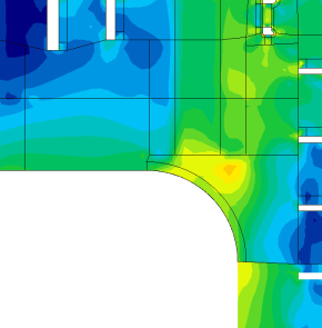
Figure 2: High Acceleration Stresses
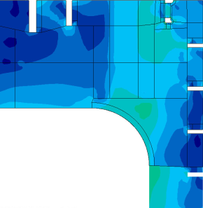
Figure 3: Low Acceleration Stresses
Fourth, the points in the structure with the most significant range between maximum and minimum stress in the FEA results are identified. Subject matter expert opinion can be very valuable at this point, as similar stress ranges will have different impacts on different categories of structural details. This variance is due to orientation of stresses with respect to joints, weld geometry, etc.
Fifth, fatigue S-N curves are applied to stress ranges, using the total planned lifetime cycles for N and stress range scaled to the expected wave height for S. Identifying significant stress ranges is easiest using the maximum expected loads. But the structures will not be cycled for their entire life at their maximum.
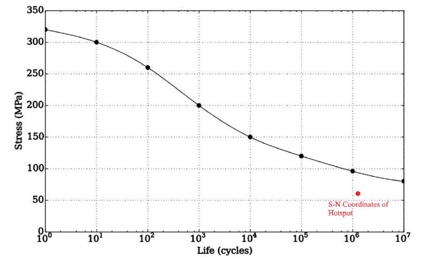
Figure 4: S-N Curve
Here the mathematical concept of expected value is useful. This is a representative wave height, where for a lifetime of X cycles, this wave height and resulting set of stress ranges has the same fatigue impact as X cycles distributed over the sea spectra defined in the first step. We scale the maximum stress range by the ratio of the maximum wave height to this expected wave height. This leaves us with a single S-N point that can be plotted against the S-N curve for the material to assess the proximity to the fatigue life.
Lastly, areas where the fatigue life is inadequate can be redesigned. Mitigations can include adding material, eliminating details that lead to stress concentrations, or altering details to improve the category of structural detail with respect to fatigue performance. This last can include things like more stringent weld schedules, refined finishing techniques, or altered joint geometry.
This general process can be adapted and tailored to a broad range of forces and loads on structures, spectra of loads or accelerations, structural details, etc. Bristol Harbor Group has applied these techniques to vessel hull structures, cargo securing systems, cranes, and other marine structures. At the end of the analyses, designers, clients, and operators can all have greater confidence in the long-term reliability of their maritime structures.

A collection of stories from guest authors.